|
Programmable Basic controller
Tiny Basic Controller (TBC) is a simple device that can operate
as a PLC (program logic controller) for home automation, control, etc. For example, this one can
dial-up by modem to the remote computer and send the status of the controlled system,
can control some processes, temperature regulation, battery charging, can
be used for educations and hobby purposes.
TBC has analogue and discrete input/output and an RS232 interface
to communicate with other devices and to reflash a control program.
The control program is a text version of BASIC language.
The main task of the controller is to interpret BASIC commands.
The TBC version of the BASIC language has commands to operate with discrete I/O, ADC and PWM.
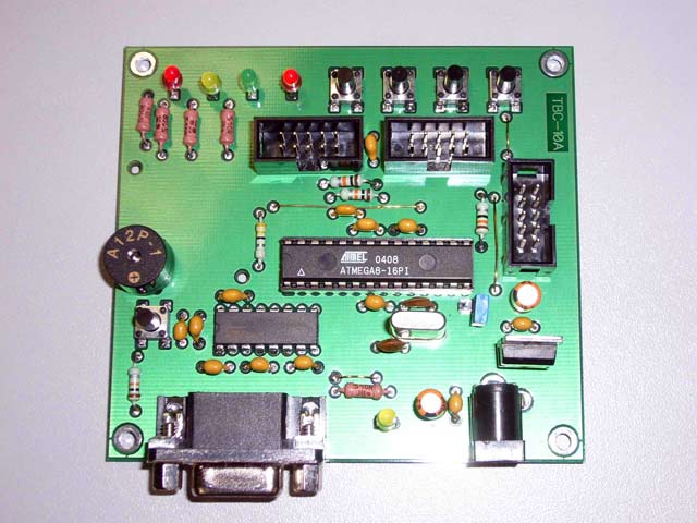
The view of controller PCB is shown below in the figure 1.

Figure 1
Technical details:
| 1. Number of discrete inputs TTL or 5V CMOS | 4 |
| 2. Number of discrete outputs TTL or 5V CMOS | 4 |
| 3. Number of analogue inputs 0…5V | 2 |
| 4. Number of PWM outputs | 4 |
| 5. Communication by RS232: | |
| Baud rate, bps | 57600 |
| Number of data bits | 8 |
| Number of stop bits | 1 |
| Parity bits | none |
| Flow control: | |
| 6.Flow control: | |
| At BASIC program downloading stage | hardware |
| At operating stage | none |
| 7.The language of embedded interpreter | Tiny-Basic |
| 8.Size of user program area, bytes, more than | 2000 |
| 9. Simple command operating time, less than uSec | 500 |
| 10 Basic program storage place | Program Flash |
10-bit PWM has frequency 5.4 kHz.
10-bit ADC Conversion time is about 30 usec, but real sampling depends of program loop.
Current through discrete outputs must be limited up to 20 mA.
Note that an LED is connected to each of discrete outputs. The current is about 8 mA per LED
The controller schematic is shown in the Figure 2.
Figure 2
Schematic in PDF format
Schematic and PCB in P-CAD 2002 format
Gerbers
Short description of schematic:
U3 is AVR microcontroller ATMEGA8.
The control program with thr BASIC interpreter for this controller is programmed by ISP after
PCB is assembled.
The firmware can be downloaded from here.
We used PonyProg programmer
(http://www.lancos.com/prog.html)
connected through the connector XP3.
The Figure 3 shows how the fuses bits should be programmed.
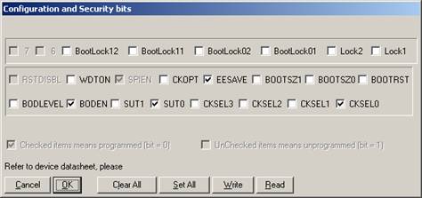
Figure 3
U1 is TTL/CMOS <-> RS232 transceiver
U2 is 5V voltage regulator
LS1 is a buzzer. This one can be any system buzzer.
Make sure that the current drawn by pin U3:5 is be limited to 20 mA.
To prevent the user program from erasing there is the jumper JP1.
When it is closed re-flashing of the user program is disabled.
LEDs D1…D4 indicate state of discrete outputs.
LED D5 indicates the program state. When the program is run the D5 is turned on.
When D5 is turned off it can mean that program is stopped or waiting for
input (INPUT command) or a delay (DELAY command).
Push button switch SW1 controls the RESET line of microcontroller ATMEGA8.
Push button switches SW2…SW5 are used as test signals for debug purposes.
To connect external circuits there are connectors XP1 and XP2.
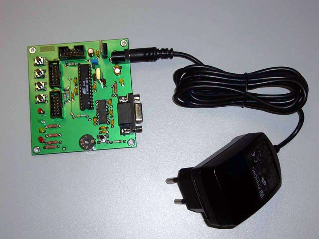
TBC as a Black Box is shown on the figure 4.
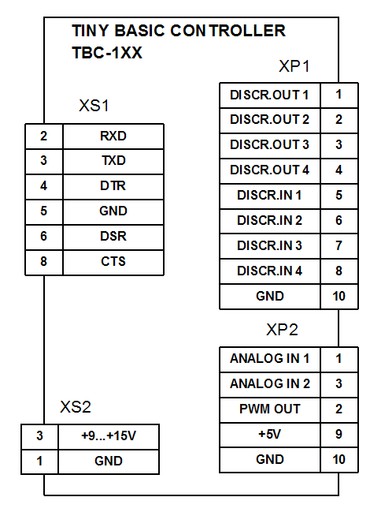
Figure 4
It is a good idea to use a socket for U3 then the full PCB can be used as a programmer
for a minimal systems based on TBC. The minimal system consists of AVR-microcontroller,
three capacitors and a crystal oscillator plus the user circuit, of course.
The PCB layout is show in the figure 5
Figure 5
The assembly diagram is shown below
Figure 6
Specific pins control commands and commands SCALE and REM were added to
the Tiny Basic specification.
Console input/output is kept the same as it was years ago. We can now use a PC with
running HyperTerminal as a console. A console is required when programming or
or if the program uses the INPUT or PRINT commands.
HyperTerminal or another terminal application must be set up as shown below:
| Baud rate | 57600 bps |
| Data/Stop bits | 8/1 |
| Parity | None |
| Flow Control | Hardware |
| Terminal emulation | ANSII / VT100 |
| Add sent CR with LF | |
User program downloading
There are two ways to download. The first one is by using the text file sending
option of the terminal. The second way is downloading using paste from the
clipboard if you are using Windows HyperTerminal, for example:
1.Make sure that jumper JP1 is open.
2.Connect TBC to PC by RS232 cable.
3.Power it up.
4.Start terminal application.
5.Press the reset button on the TBC.
You now have one second to send SPACE or ENTER from the terminal. SPACE is for download
BASIC application and ENTER is for list current BASIC program. When the one second
interval has expired the current application starts. If you hurry to send SPACE,
after reset button is pressed, you get the message “Reflash…” on the screen of
the terminal. You must send the program text by paste from clipboard or text sending
option. TBC outputs a “W” symbol for each 64-bytes block flashed during of programing
operation.
If you press SPACE instead of Enter, for list the current program, just press
the reset button to cancel the reflash operation.
The method of working with the TBC and a console is shown below.
At first you should create program text in the notepad.
Then copy the whole text to the clipboard.
Figure 7
Press the reset button on the TBC. There is a one second interval to send the
SPACE symbol to theTBC to activate the downloading process.
Figure 8
Send text by terminal
We can now see the re-flashing process
Figure 9
When the re-flashing process is finished the message “OK” is sent.
To start the application press the reset button, after a one second
interval, the application will run.
You can see that you only need to have simplest editor and terminal
in "your kitchen" to program the TBC.
You can use a palm size PC as well. A PDA console is shown below:
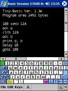
Figure 10
Controller version of Tiny Basic
Numbers
All numbers are signed integers and must be between -32767 and 32767.
Variables
There are 26 variables denoted by the letters A through Z. These are
represented internally as 16-bit, two's-complement integers.
Arithmetic operators
All operations are performed to 16 bits of precision. Arithmetic operations
which overflow 15 bits of magnitude will produce an error message.
The arithmetic operators are:
+ addition.
- subtraction.
* multiplication.
/ integer division (note that 14/5 = 2).
% remainder from division (14 MOD 5 = 4).
& bit-wise logical AND (3 AND 6 = 2)
| bit-wise logical OR (3 or 6 = 7)
Arithmetic operations result in a value between -32767 and 32767.
Compare Operators:
> greater than.
< less than.
= equal to.
Note that compare operators can not be used in expression.
Expressions
Expressions are formed with numbers and variables with
arithmetic operators between them. Operations are performed with three levels of precedence. The first step is to perform Unary
operations (+, -), then Multiplicative operations (*, /, %, &),
additive operations (+, -, |).
Within each precedence level, the value of an expression is computed from
left to right. Parentheses can also be used to alter the order of evaluation.
Labels
Label is a set from 1 to 3 digits. Labels must be set before line
that is a point to jump or is a start line of subroutine.
Syntax:
| PRINT | linefeed (LF) and carriage return (CR) added to the output |
| PRINT var | Send variable in decimal form to the console and add CR and LF |
| PRINT "message" | Send message to the console and add CR and LF |
| PRINT x,y,z, | Send list of variables, comma inserts number of spaces to set output
to the next position of tabulation.
Comma at the end of line cancel
adding CR and LF |
| PRINT x;y;z; | Send list of variables and string. Semicolon allows output more than
one variables or strings at one line.
Semicolon at the end of line cancel adding CR and LF |
| PRINT "$";y; | $-version of PRINT command. It allows send single symbol by symbol code.
Semicolon at the and of line cancel adding CR and LF |
Syntax:
| INPUT var | Output “?” and waiting for input value. Puts value
to variable X after receiving CR |
| INPUT "prompt",var | Output prompt and waiting for input value.
Puts value to variable X after receiving CR |
| INPUT "$",var | Waiting for a single symbol.
Put symbol code to variable C |
Syntax:
| IF condition THEN expression | If condition is true expression is calculated |
| IF condition THEN GOTO label | If condition is true execution goes to line with label |
| IF condition THEN GOSUB label | If condition is true subroutine with label is called |
Syntax:
FOR var=start_value TO end_value
REM Put statements here
NEXT
| Execute a block of statements a number of times.
number = end_value - start_value + 1
|
Syntax:
| GOTO label
| Jump to the label.
|
Syntax:
| GOSUB label
| Call subroutine labeled as label
|
Example:
| |
REM Example
|
Syntax:
| RETURN
| Return from subroutine
|
Syntax:
Syntax:
| ADC var
| Read current channel of ADC and put value into variable
|
Syntax:
| DAC expression
| Output result of expression to PWM channel
|
Syntax:
| SETB expression
| Set bit that number is defined as result of expression
|
Syntax:
| CLRB expression
| Clear bit that number is defined as result of expression
|
Syntax:
| TSTB variable,expression
| Read bit that number is defined as result of expression and put value to the variable
|
Syntax:
| DELAY variable,expression
| Form delay that duration in msec is result of expression
|
Syntax:
| SCALE variable,multiplier,divider
| Operator of scaling. Does actions:
1.TMP32 = variable * multiplier
2.variable = TMP32 / divider
|
Syntax:
| STOP
| Stop operator. Use for debug purpose in simulator
|
Syntax:
| REM Just a comment
| Comment operator. Interpreter does not execute this line
|
TBC system bits
Input bits
Bit
number |
Description |
| 1
| Discrete input #1
|
| 2
| Discrete input #2
|
| 3
| Discrete input #3
|
| 4
| Discrete input #4
|
| 126
| Flag that signals about data in the console buffer
|
Example 1. The program does an infinite cycle that reads the state of bit
and outputs the state to the console
| |
100 TSTB X,1
IF X=1 THEN PRINT “1”
IF X=0 THEN PRINT “0”
GOTO 100
|
Example 2. The program reads the state of the console and executes
some background tasks. If there is a data in the console buffer it
starts the execute INPUT command to read the data and output it to the console.
| |
10
rem Do something else as background task
tstb a,126
if a=0 then goto 10
input "$",b
print "$";b;
goto 10
|
Output bits
Bit
number |
Description |
| 1
| Discrete output #1
|
| 2
| Discrete output #2
|
| 3
| Discrete output #3
|
| 4
| Discrete output #4
|
| 127
| Sound enabled/disabled – 1/0
|
| 128
| Switch to ADC channel:
0 – channel #1
1 – channel #2
|
Example. The program forms double beep
| |
GOSUB 200
GOSUB 200
END
200 SETB 127
DELAY 100
CLRB 127
DELAY 100
RETURN
|
Runtime diagnostic
The interpreter does runtime diagnostic. Whenever an error occurs, execution
is stopped and a message with an index of the error is sent to the console.
Index
of error |
Description |
| 0
| Syntax error
|
| 1
| Unbalanced parentheses
|
| 2
| No expression present
|
| 3
| Equals sign expected
|
| 4
| Not a variable
|
| 5
| Label table full
|
| 6
| Duplicate label
|
| 7
| Undefined label
|
| 8
| THEN expected
|
| 9
| TO expected
|
| 10
| Too many nested FOR loops
|
| 11
| NEXT without FOR
|
| 12
| Too many nested GOSUBs
|
| 12
| RETURN without GOSUB
|
Samples
1.The "Color" test
| |
PRINT "$";27;"[1;32;40m";"$";27;"[2J";"Color Test Ver. 1.0"
for j = 40 to 47
for k = 30 to 37
PRINT "$";27;"[1;";k;";";j;"m ";k;";";j;
next
print
next
PRINT "$";27;"[1;32;40m"
PRINT "ОК!"
|
The result of the program is shown below.
Figure 11
1. Running Light
| |
rem *********************************************
rem *            Running Light
rem * State of bit #1 defines  running direction
rem *********************************************
print
print "**************************"
print "* Running light *"
print "* 23.06.2006 TbcGroup *"
print "**************************"
100
for i=1 to 4
tstb y,1
x = 5-i
if y=1 then goto 400
x = i
400
setb x
delay 100
clrb x
next
delay 200
goto 100
|
2.Semi-automatic Elbug Key
This Elbug Key has the function of a CW VOX. “Input” changes of speed
and hold delay is achieved by measuring the voltage on the variable
resistors as shown in the figure 12.
Figure 12
| |
rem *********************************************
rem * ELBUG KEY
rem * d – dot delay
rem * p – PTT hold delay
rem * t - "monostable" of hold delay
rem * Output bits:
rem * #1 - manipulation
rem * #2 - PTT
rem * Input bits::
rem * #1 - dot
rem * #2 - dash
REM ******************************
REM * 10 start sending program   *
REM ******************************
REM
PRINT
FOR I=1 TO 10
PRINT "*";
NEXT
PRINT

rem * Analog inputs:
rem * #1 - var. resistor "Manipulation speed"
rem * #2 - var. resistor " PTT holding delay"
rem **********************************************
print
print "**************************"
print "* ElbugKey Version 1.1 *"
print "* 23.06.2006 TbcGroup *"
print "**************************"
50 clrb 2
100
adc d
d=d+15
setb 128
tstb A,1
if a=0 then gosub 200
tstb a,2
if a=0 then gosub 300
adc p
p=p+50
clrb 128
if t=0 then goto 50
t=t-1
goto 100
rem ------------------
rem  Dot subroutine
rem ------------------
200 setb 1
setb 2
t=p
setb 127
clrb 3
delay d
clrb 1
clrb 127
delay d
return
rem ------------------
rem   Dash subroutine
rem ------------------
300 setb 2
setb 127
setb 1
t=p
delay d
delay d
delay d
clrb 1
clrb 127
delay d
return
|
3. Automatic calculator for an SWR-meter
The schematic of the SWR meter (calculator part) is shown below
Figure 13
Short description
Analogue inputs receive normalised signals from the reflected wave and the forward
wave detectors. Levels of these signals are 5 volts at maximum power. Calculated
SWR is output on the anologue meter by PWM.
Position “С” of the mode switch is the test position for calibration at the manufacturing stage.
For calibration do operation:
1. Start the terminal program
2. Power up the TBC. Input signals are not needed for this operation.
3. Input the value -1 by the console. PWM will be set to the value 1000
4. Adjust resistor R1 for full scale deflection
This resistor can be calculated by formula:
R1 = 0.976 * U/I – Rр,
where:
U – controller VCC
I – current of full scale deflection
Rp – analogue meter internal resistance
5. Inputs value of SWR for scale calibration
Description of some variables
N – number of samples for average;
K – defines scale zooming
Last point of scale defined as
SWR = (10+K)/K
Zero point corresponds SWR=1
K=1, last point of scale 11
K=2, last point of scale 6
K=3, last point of scale 4.333
K=4, last point of scale 3.5
K=5, last point of scale 3
K=6, last point of scale 2.666
| |
PRINT
PRINT "**************************"
PRINT "* SWR-meter Version 1.0 *"
PRINT "* 24.06.2006 TbcGroup *"
PRINT "**************************"
N=10
K=4
50 CLRB 1
F=0
R=0
FOR I=1 TO N
CLRB 128
ADC A
F=F+A
SETB 128
ADC A
R=R+A
NEXT
F=F/N
R=R/N
TSTB A,1
IF A=0 THEN GOSUB 100
TSTB A,2
IF A=0 THEN GOSUB 200
TSTB A,3
IF A=0 THEN GOSUB 300
TSTB A,4
IF A=0 THEN GOSUB 400
IF D>1023 THEN D=1023
DAC D
GOTO 50
REM---------------------------
REM     SWR output
REM---------------------------
100 X=F+R
Y=F-R
IF Y=0 THEN GOTO 110
SCALE X, K*100, Y
PRINT "F=";F;" R=";R;" SWR=";X/K
D=X-K*100
RETURN
110 SETB 1
DELAY 250
PRINT "SWR can't be calculated"
D = 1023
RETURN
REM---------------------------
REM   Forward output
REM---------------------------
200 D=F
PRINT "F=";F
RETURN
REM---------------------------
REM     Reflected output
REM---------------------------
300 D=R
PRINT "R=";R
RETURN
REM---------------------------
REM     Calibration
REM---------------------------
400 INPUT "SWR=",X
D=K*(X-100)
IF X=-1 THEN D=1000
PRINT D
RETURN
|
4. PID regulator
This is an outline program to learn PID regulators. The external connections to the
basic-controller and block diagram are shown in figures 14 and 15. The program has
an automatic switch of reference. It allows you to watch the signal on an oscilloscope.
You can turn logging on in terminal program to output to a file.
Finnaly you will get text that can be converted by EXCEL to a diagram like
the one shown in figure 16.
Figure 14
This schematic and program outline has an automatic switch of the reference.
Figure 15
| |
REM *********************************************
REM *          PID-regulator                    *
REM * P,I,D are scaled by very strange way      *
REM * for example, 1/tau for integral chain is  *
REM * a 100 devided by requested factor,        *
REM * signal for regulator is devided by 10, so *
REM * for 1/tau = 0.5 you need enter            *
REM * 10/0.5=20 as a factor                     *
REM *********************************************
PRINT
print "******************************"
print "* PID-regulator rev. 1.1     *"
print "* 29.06.2006     TBC Group   *"
print "******************************"
   X=800
50 input "PROP FACTOR=",L
   input "INTEG FACTOR=",M
   input "DERIV FACTOR=",Q
I=0
100 GOSUB 300
    SETB 128
    ADC Y
    Z=(X-Y)
TSTB B,1
IF B=1 THEN GOSUB 800
D=0
TSTB B,2
IF B=1 THEN GOSUB 900
GOSUB 700
C=(P+I+D)/10
PRINT Y
REM PRINT "X=",X;" Z=",Z;" P=",P;" I=",I;" D=",D;" C=";C," O=",O
   IF C<0 THEN C=0
   IF C>1023 THEN C=1023
   DAC C
TSTB A,126
IF A=0 THEN GOTO 100
input "$",A
PRINT
PRINT "PROP=",L;" INTEG=",M;" DERIV=",Q
GOTO 50

REM ******************************************
REM *      Reference signal switcher         *
REM * Every 50 samples it switches reference *
REM *            signal                      *
REM ******************************************
300 S=S+1
    if S=50  then goto 330
    if S=100 then goto 380
    return
    REM Set Reference signal to 200 units
330 X=200
    return
REM Set Reference signal to 800 units
REM and start samples counting
380 X=800
    S=0
    return

REM *********************************
REM *        Proportional           *
REM *********************************

700 P=Z
    SCALE P,100,L
RETURN

REM *********************************
REM *         Integral              *
REM *********************************

800 J=Z
SCALE J,100,M
    I=I+J
RETURN

REM *********************************
REM *        Derivative             *
REM *********************************

900 D=W-Z
    W=Z
SCALE D,100,Q
RETURN
|
Figure 16
Simulator
Simulator is a program for Windows 98/NT/XP. It allows you to write and debug a program
without programming real controller. Simulator can simulate the controller resources
except the beeper. Simulator console does not recognise the ANSI ESC codes.
Simulator allows run program, stop, execute step-by-step, watch variables and resources.
To stop the program at specified places you need to insert STOP commands after required line.
The Simulator window is shown below:
Figure 17
All of the controller resources are shown on the screen.
The debug process is controlled by the four buttons:
F9 – start program
F2 – force program stop. After stopping the program can be continued by pressing button F9
F8 – step-by-step execution
F4 – simulator reset
Inside the edit window standard operation Ctrl+C, Ctrl+V,Ctrl+Z are allowed.
Simulator can be downloaded from here.
___________________________________
By
Alexander Kostyuk ua6ann@mail.ru
Evgeny Fadeev rv3bj@hotbox.ru
|