|
|
||
|
\главная\р.л. конструкции\... |
A simple wideband FM 10GHz transceiver with 30MHz I.F. by G3PHO
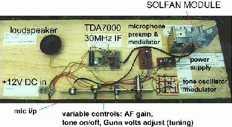
The photo above shows a "breadboard" version of the simple wideband 10GHz transceiver described in this article. The basis of the transceiver is the SOLFAN DOPPLER MODULE shown in the top right corner of the photo. This actual breadboard was used as a demonstration item at a lecture given by the writer to his local amateur radio club. Obviously you wouldn't use it in this form on a portable expedition into the hills! However, you can clearly see the several, simple boards that are added to the Solfan to make it into one of the simplest little rigs you could hope to make for the microwave bands.
If you make all the individual modules shown above, mount them all together in a metal box (an Eddystone diecast box is recommended). You then need an antenna and a support (eg tripod) to complete your 10GHz transceiver.... the choice is yours but some suggestions are given later.
IMPORTANT NOTE.........
When making up the finished transceiver do make sure that you have the polarisation of the waveguide output correct for your part of the world. I'll explain................
In Europe we all operate with the waveguide narrow face in the horizontal position. This makes the diodes in the cavity and the RF out being in horizontal polarisation (check by looking into the cavity from the horn end... with the power off!). In other parts of the world (eg. new Zealand) you may find the waveguide is mounted so that the broad face is horizontal, thus putting the diodes and resultant polarisation of the RF output in the vertical. The writer knows of more than one case where a new microwaver was puzzling over the absence of received signals until it was pointed out that he was crossed-polarised with the other station. Polarisation is very important at microwaves! In the breadboard rig shown above, the Solfan is mounted to give horizontal polarisation, the norm in Britain.
Note also that the only "complicated" module in the photo above is the receiver IF. It is built on a purpose-made pcb. All the other units can be made on perforated stripboard (eg. "Veroboard") or built "dead bug" fashion on a small piece of single side pcb. The receiver IF shown in the photo uses a prototype of the board shown in more detail below. It might be possible to build the receiver on an unetched pcb, using the "deadbug" or "ugly" style of construction but the writer has not tried this and you might have instability problems. However it's worth a try!
Other Gunn oscillator/mixer modules can be used. The connections shown in Figure 2 will generally be the same but make sure that the Gunn module is "NEGATIVE EARTH".
To put a Solfan doppler module
into amateur radio use:
Of course, lots of other ancillary circuits may be included, especially a small post amplifier stage between the receive mixer diode and the IF unit. This provides a better match between the 200 to 300 ohm impedance of the diode and the input impedance of the IF (usually 50 ohm). These can come later though... you'll have plenty to keep you busy from the start!
The following diagrams and text describe a complete, easy-to-make, 10GHz wideband transceiver based on a Solfan module. The design includes all the points made above. Construction is relatively straightforward, especially the power supply/microphone amplifier and tone oscillator sections which can be built on veroboard or other prototype medium. The 30MHz IF, however, must be constructed on a printed circuit board, preferably double-sided.
You are not limited to the IF shown. With the Solfan module, any IF from 10.7MHz to 50MHz can be used. A higher IF will give disappointing results since the mixer diode mount on the Solfan has too much capacitance to ground at VHF frequencies, resulting in a great loss of the IF signal.
Other doppler modules designed for the 10 to 11GHz region may work at VHF IFs... you will just have to experiment ... that is what being a microwaver is all about! With these you could, for example, use a surplus FM broadcast radio. Either find a clear frequency between 88 and 108MHz or just tap in to the 10.7MHz IF section of this and disable the VHF "front end".
The 30MHz IF receiver described here will give
very good results and is recommended to anyone who can get the PCB made for
them. The art work for the pcb is also provided. It can be saved as a GIF graphic
file and scaled to the dimensions shown by using a graphics software package
such as Paint Shop Pro or Corel Photo.
The following two diagrams show the general construction of a Solfan Doppler module, together with the components that are usually found soldered to its various terminals.
In the diagram above, the capacitors are all small disc ceramic types.
POWER SUPPLY/MODULATOR/TONE OSCILLATOR CIRCUITS:
If you cannot obtain BC182 or BC108 transistors
you can use 2N2222 types throughout.
The 1uF tantalum capacitors should be soldered as near as possible to
the LM317T input and output pins.
It is also worthwhile fitting protection against accidental input voltage polarity reversal (not shown in the circuit here).
The LM317T output (a variable voltage modulated
by microphone audio or a 1kHz tone at the flick of a switch) is fed directly
to the Gunn diode + terminal.
A 30MHz RECEIVER I.F. (based on the TDA7000 FM receiver IC):
FIGURE 4:
Please note: There is no C16 in the above circuit.
For full loudspeaker audio
an LM380 audio amplifier chip is used in the following circuit:
The PCB layout below combines the TDA7000 IF with the LM380 audio amplifier to produce a complete 30MHz receiver, suitable for use as a "back end" to the 10GHz Solfan module:
The parts layout for the above PCB can be seen below:
All the individual boards shown above, plus the Gunn module can easily be fitted in a metal box. The waveguide output section can be extended with a short length of waveguide fitted with flanges at each end. This can protrude from the box so that a variety of antennas can be used. For your first venture into microwaves it is suggested that you use the small horn that came with your Gunn module. This should give very strong signals over line of sight paths of a few kilometres. Changing to a dish of modest size (say 35cm) will increase your potential line of sight contacts by dozens of kilometres.
Before all of that though you have to get your newly built 10GHz transceiver working. Follow this link to the next step!
![]()